Welcome to LDCad
About 
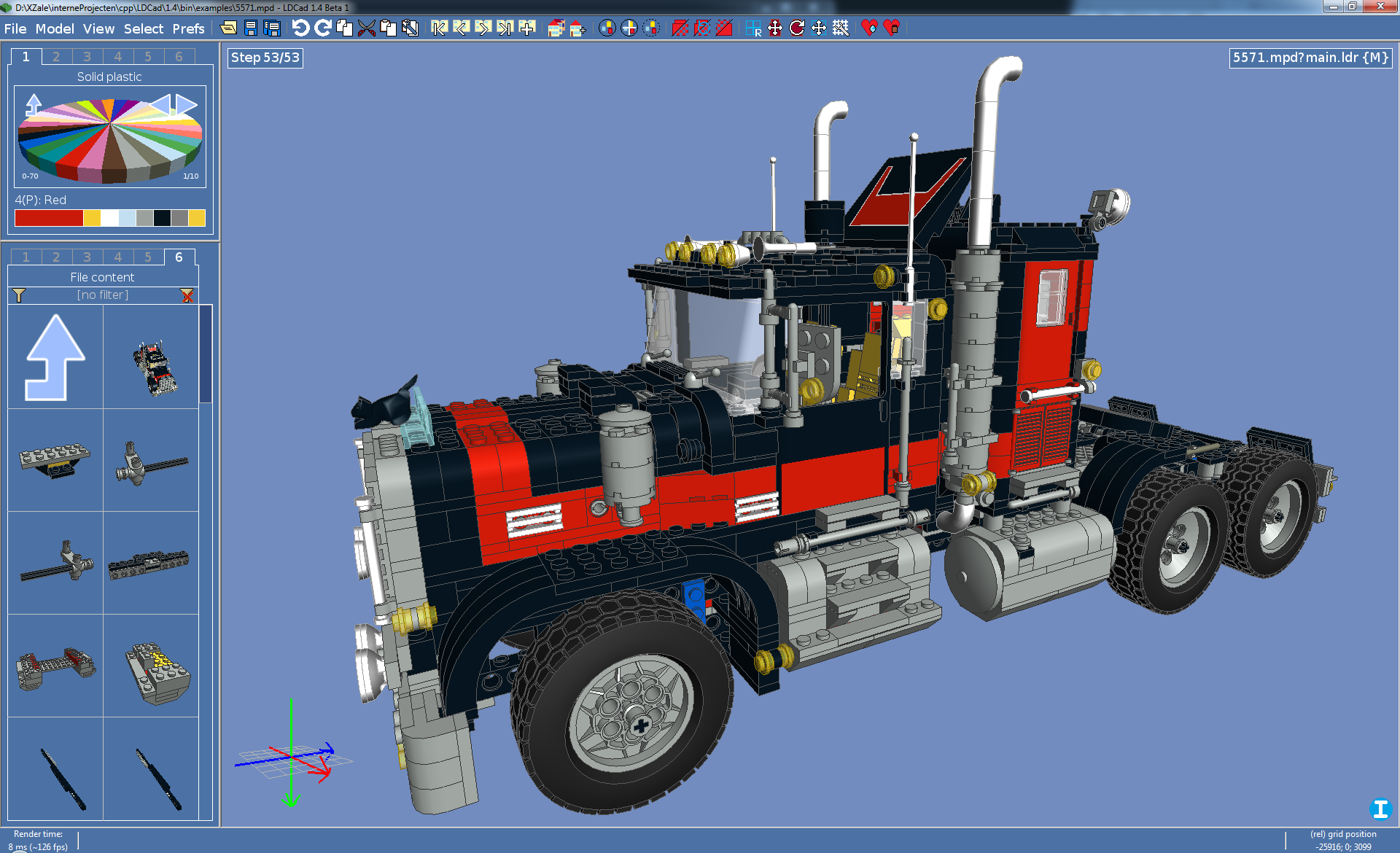
LDCad is a multiplatform LDraw (virtual LEGO) editor that lets you edit LDraw model documents in real-time, it's main features are:
For those that are new to LDraw, it's highly recommended that you take a close look to the project's home site LDraw.org and it's forum. When ready to start with LDCad, it's also highly recommended you read the below 'quick manual' first to get the most out of the application without to much of a hassle. Any questions, suggestions or bug reports concerning LDCad are also welcome, just mail them to rmelkert@chello.nl. Requirements Based on dependencies and tests, the minimum requirements more or less are:
The above is only a suggestion, For example I've seen it work on a 10 year old Pentium 4 laptop using a mobile radeon 7500 with some minor limitations. To get the most out of the application the following should be considered:
Download LDCad Below are all versions of LDCad currently available, in most cases it's best to get the top (latest) one for your platform. Most versions are available in both a setup and an archive package. The archive versions are aimed at the more advanced users whom want to take a look at the application without installing stuff. Most users will be best off using the setup version if available. At the moment Linux is only available in the archive variant, due to it's many distobutions. I will try to add setup solutions for some platforms in the future. But for now only a compressed tar ball will be available. Before downloading you might want to read the "Quick manual" or at least the "Getting started" sections below. General usage notes:
Don't forget to check the 'known issues' section when you are heaving problems using LDCad.
Linux notes The current Linux version is a work in progress. I can't tell on which platforms it runs, cause I don't know my self as a result of there being so many. Also current version is 32 bit only, a 64 bit version should follow at some point. In the mean time if you absolutely want to use it under 64 bits, you might want to look into a chroot environment (untested though). Below are the platforms I have tested myself or people reported it working on:
Quick manual This manual assumes you are using the latest versions of both LDCad and the LDraw library. Getting started Be sure you have the latest LDraw library installed, before you get started with LDCad. After downloading LDCad, run the setup and start LDCad from the start menu. On first start the application will ask you to agree with the LDCad license, after a positive response you need to supply the LDraw library location. For this you will be presented a directory browsing dialog, use it navigate to the location you installed the LDraw library in (e.g. "c:\program files\LDraw"). nb: The LDraw library folder is the one holding the "parts" and "p" sub folders. When the program is done reading the library, you will be presented with the main application window. In the left panel you might see 'Updating content, please wait' for some moments (Couple of minutes on older hardware). This is due to background work the application needs to do whenever the library dependencies change (first start/library update). When the application is fully done, the message will disappear and you'll be ready to start using LDCad for real. Overview The application is basically a single graphic window, which is divided in three major sections.
There's also a two line status panel at the bottom that shows you as selection of information, and displays hints about the object the mouse is over. While working with the three major areas, it's very important to remind the position of the mouse cursor dictates interaction at all times. For example if you have it inside the color bin pressing the up arrow will scroll the items in the current color bin menu. On the other hand when the mouse is inside the part bin area the same arrow key will scroll the items inside the part bin. Same goes for the mouse wheel and all other keyboard commands. Right clicking inside any of the main areas will open a menu, by default it will show items relevant to the area you clicked in. (e.g. color bin stuff inside the color bin area). But any open menu can be used to navigate to any other menu afterwards by using it top icons. The most important menu is the 'session' menu. You open that by clicking inside the editing area and click on 'session'. The menu contents will change and the resulting menu will give you access to session management. A session is basically a model and it's working environment. LDCad uses a session menu instead of a simple 'file' menu because a single LDraw file can hold multiple models. Sessions are automatically started for all (sub)models in a LDraw file when you open a file using 'Open file'. Starting a new file will create a session for that file's first (or only) (sub)model. The session menu can also be used to switch between sessions, this way you can work on as many file/models you want without having to start multiple LDCad instances. Do note clicking 'Save current file' will save the file in which the current session model lives. By doing so it indirectly saves all other (sub)models in that same file. Most items in this menu should be clear, the others you won't be needing when getting started with LDCad. The same goes for most other menu's. Working with the bins During editing you will be working with hundreds of different LDraw parts in dozens of different colors. To make this easy you use the color and part bins you'll find at the left of the screen. Let's start with the color bin. On start up it displays a list of color groups, this let's you choose the general kind of 'color' you want to use in your next editing activities. Most of the time you will be working with 'normal plastic' parts so click on the 'all solid plastic' item to open the group containing all normal colors. Doing so will change the color bin from a menu to a color wheel selector. The 'wheel' displays up to 32 colors you can click in order to use it. If there are more then 32 colors in the group you can navigate trough it's pages using the buttons at the top left of the wheel. You can go back to the group overview by clicking the icon in the top right of the wheel. When ever you click on a color on the wheel the color bar at the bottom of the color bin area changes color accordingly. This bar displays (from left to right) current 'working color' and the last couple of used colors. You can click on any of the recent used colors to make then the 'working' color again. When working with a lot of different colors in a single model it can be a bore to change the group (page) all the time. To prevent this you can use up to six different groups at once without having to 'navigate' trough the color group menus every time. This is done by clicking on the '1'..'6' labels at the top of the color bin area. These are 'views', you can navigate to a different group in each of these views and change between views in order to revisit the group they point to. Next is the part bin, it works much like the color bin in way of navigating. But instead of menus and wheels it uses a grid in which the items of the current group are displayed. At first it will display the 'root group' this is the top most group which divides the parts into major sections. It also gives access to some 'special groups and parts'. Most important groups to get started with are the fist two. One shows parts sorted into manageable groups by function (like: Plane bricks, Bricks with stickers, Plates, 45 deg slope bricks, etc) the other in major categories (like: Technic, Train, Doors, (all) Bricks, (all) Plates). By clicking on any of the items in the part bin grid you go 'inside' that group and it contents will replace the current items in the grid. This can go on multiple levels until you click a item that isn't a group itself. Such a item represents something you can use in your model (e.g. a 2x4 brick). The last non group item clicked becomes the 'working part', and will be used in editing actions. Also note most parts will be drawn in the current 'working color' you selected in the color bin. Some groups can have many parts, which could slow down finding a specific part (e.g. a 1x10 brick within the bricks group). To help with this all groups have a filtering mechanism you can use to limit the items displayed to those with specific keywords. You activate the filter by typing a phrase, to filter on, while the mouse cursor is inside the rectangle which reads '[no filter]' at the moment. For more advanced filtering possibilities click on the same area in order to open the filtering dialog. With it you can control how items are matched in more detail. Even with all the groups organizing available parts into manageable chunks and their filters, it can be fiddling to find a specific part. For those hard to find parts there is a special 'search' group accessible from the root group. The search group looks just like other groups except it's filter will be applied on all parts in the library, and no items will be shown when there is no filter text given. As with the color bin the part bin also has multiple views you can use to switch between different groups more efficiently. Placing and manipulating parts Placing a part isn't very hard you just 'drag' them from the part bin into the editing space. When you release the mouse button it will be placed in the model at the location it was show during drag. If there is no active session/model open in the editing space you will be asked to start one. And afterwards the part will be placed at the center of the (empty) model. A part is always placed using the current 'working color' (the color you choose with the color bin). Adding a part can also be done using the 'ins' key in that case the 'working part' will be used (also in the 'working color'). When placed you can move existing parts in your model by simply 'grabbing' them and moving the mouse around while holing the mouse button down. While adding a couple of parts you probably noticed you can only place parts at one 'level' by default. This is because although the editing view displays the model in 3D you can only manipulate things in 2D (because the mouse can only go left/right up/down). To stack parts on top of other parts you must change the current 'editing grid', this is the level (base plate sort to speak) parts are currently placed on. This is done using the compass. The compass is the red/green/blue cross you see in the bottom left of the editor view. It displays the 'world' orientation. When you move your mouse over it, it will zoom into a larger version you can use to change a number of 'grid' settings. In the center of the larger version of the compass you'll see rectangular gray regions. Clicking on them will change the 2D grid to 'font/back', 'sides' or 'top/bottom' mode. Up to now we have been working in 'top/bottom' mode. It might seem a hassle to change the grid mode all the time but you will learn to use it efficiently (e.g. building in layers) over time. Also there are keyboard shortcuts for changing the mode. After changing the grid to e.g. 'sides' you can place a brick on top of the last clicked brick. Working in only two directions at once means you often have to position parts in two steps. First add it at the right 'level' then move it around in a different grid mode to get it at the correct location. You can place new parts much more efficiently by using the 'working position'. The 'working position' is the position last used. This position is used to initialize any new part when it's added. Because the working position applies all dimensions (width/height/depth) parts will be inserted in line with last used parts. E.g. at the same level when in 'top/bottom' grid mode. Or at the same depth when in 'front/back' mode. You can use this to limit the number of grid mode changes. For example you are in 'top/bottom' grid mode and need to add bricks higher or lower then the ones you placed last. You could change the grid to 'sides' and add a part a the correct height, and switch back 'top/bottom' to move it to it's final position on that level. The smarter (and correct LDCad usage) approach is to click a part already on the correct height and then drag the new part in one go to it's new position. So now you know how to add and move parts in all three dimensions, but they're all oriented the same. Which makes building e.g. a house very hard to do. So you'll be needing some way to rotate parts in your model. This is where the 'editing pin' comes into play. The editing pin is the 'umbrella' like object you see sticking out parts while a selection is active (e.g. the part you last added to the model). To rotate a part first make sure it's selected. If it's not click on it without moving the mouse. When the correct part is selected you click anywhere on the flat disc on top of the editing pin and while holding the mouse button down move to left or right. The part will rotate accordingly. When the part reaches the wanted rotation (shown in degrees) just let go of the mouse button and it becomes permanent. Rotating parts can always only be done perpendicular to the current grid mode. Also recognizable by the direction of the editing pin it self. So before rotating be sure to select the correct grid mode first. You can also rotate multiple parts as if they where a single part by selecting more then one part at once. This is done by first selecting the 'center' part as before. Next you click additional parts while also holding down the 'ctrl' key. When all parts of interest are selected you can rotate as before but now all parts rotate alongside with the first selected part. One final note about rotating, just like the last 'working position' is used for new parts LDCad also applies the last used rotation to new parts. This way adding bricks to e.g. a wall is made extremely simple, even after going around a corner. You don't need to rotate every brick 90 degrees just the first one. Same goes for it's color by the way. Besides rotating, you can also use the editing pin for moving the selection. You do this by changing the 'editing pin's mode' from rotating to moving by clicking on the corresponding icon on it's stick (above the flat disc). When in editing mode the flat disc will be replaced by a cross of arrows. Grabbing ether of the arrows will let you move the selection in only one direction. You can also move in both gird directions like normal moves by clicking using the center of the arrows. You can also move a selection of multiple parts around without using the editing pin, by simply grabbing any part in the selection as described before. Now you can add, move and rotate parts, but in many cases you also would need to delete some of them. This is done by selecting the part(s) you want gone, and simply follow with a tap on the 'del' key. Final thing you might want to know is how to change the color of parts in your model or change the part it self. Changing a parts color is done using the color bin. First select one or more parts who's color you want to change. Next make the wanted color 'working color' and click on the 'working color' portion of the color bin color bar (the largest rectangle in the selected color). Alternatively you can also double click on the color wheel to apply the chosen color in one go. To change a part (e.g. a 2x4 brick into a 2x3 brick) select the part(s) you want to change in your model. Next double click on it's replacement part inside the part bin. More about grids You might have noticed LDCad is all about (2D) grids. This is why you need to understand it deeply to make the most of the application. Up to now we have been using a fixed stepping. This could become a problem when you are trying to place a part at some precise position, it might not 'go' there because it keeps skipping over it. To place such parts you need to change the grid stepping. This is done using the compass or menu. Go to the compass in order to zoom it, at top of the compass window you'll see three numbers. These are the current stepping values for grid and rotation. Click on any of them to open the grid menu (also accessible by navigating through any right click menu). The resulting menu will display all available grid options, including changing the stepping. To fully understand the values associated with grid stepping you must have some LDraw background. Some logical values are: '20' (the with of 1x1 brick), '24' (the height of 1x1 brick without the stud), '8' (The height of a plate without the stud). Knowing these numbers meaning makes the stepping of (10/8/10) suddenly more understandable (it applies steps of 'half a brick' in the width and depth direction and 'plates' in the height direction. After choosing a finer grid you'll be able to place smaller parts that need more precision (e.g. a technic pin inside a beam). Another thing about grids is their orientation, up to no it's been 'absolute' meaning it's parallel to the models width, depth and height. But in many situations (especially when working with technic models) you would want the grid to align with the orientation of a part (e.g. a technic 1x16 brick whom is placed at a angle.). In order to place other bricks on top of the angled brick as if that brick was level you must change the grid's orientation. This is done by selecting the part you want to place stuff 'upon' followed by pressing 'o' on the keyboard. Doing this will change the grid orientation to the orientation of the selected part. Any part you will add or move next will use the new grid orientation as a guidance. As a result you can literately build a wall at an angle with the same ease as if it was level. The grid orientation is also visible in the compass, it now displays two sets of crosses. Changing the grid orientation back to 'normal' (absolute) is done by pressing 'o' while no selection is active. Epilog After reading this short manual, you should be able to draw your first model or edit existing ones. There is much more to tell about LDCad and it's additional features will only grow in the future. But in my experience most people don't bother with a manual so I'm not spending too much time on one ether. You are welcome to email me with questions. Alternatively you could post them on the LDraw forum (in the "LDraw Editors and Viewers" section) so multiple people can benefit from the information. Keyboard shortcuts Global (inside any area)
Inside menus
Inside the colorbin
Inside the partBin
Inside the editing view
Reporting bugs If you think you found a bug (the application crashed or does something it shouldn't) please report it to me so I can fix the problem in the next version. If doing so please give detailed information about what you were doing and include the problem model and contents of the 'logs' folder in the LDCad installation location if possible. Known issues Known issues [Linux only] parts are not fully drawn or appear 'in side out'. This is caused by the Open Source Readeon driver. The AMD proprietary driver doesn't have this issue. Newer versions of the oss driver might fix it in the future, I'm also still looking into this issue. The screen corrupts (seems to scale down or move up) with every redraw. This is a issue related to buffers, it is caused by an optimization 'trick' (front buffer re-usage) LDCad uses that's not always available. Disabling the feature should solve it. (some) pictures show up as white crosses. This is the fallback LDCad uses when the OpenGL implementation does not support the needed texture size. This is usually the result of a very outdated OpenGL implementation, consider upgrading the VGA driver. Opening files from root directory (e.g. c:\) will cause slow(er) loading resulting from file list caching problems. (It basically has no last modified timestamp, and thus re-caches on every query/ldraw file locate). Never place your ldraw files in the root of a drive but always in some subdirectory e.g. c:\myLDrawDocs) Closing files is not permitted. I disabled this in order to do things right the first time when it's time to implement file change detection (which also needs reloading/re-syncing of internal files to disk. Close needs this if you would say 'no' to save changes). If things get to crowded restart the application. Models using 'mirroring' or 'scaling' will not render correctly. This is because it will mess up normals and or BFC information. In practice it's best not to use mirroring at all because it causes 'unrealistic' usage (e.g. can't do it with real Lego). Otherwise it's not really a problem besides the degraded rendering quality.. [Linux] Splash and license agree dialogs might not be centered correctly. This happens on some multimonitor setups and is the result of a third party bug I can't fix myself. | ||||||||||||||||||||||||||||||||||||||||||||||||||||||||||
Copyright Roland Melkert 2011, all rights reserved. | ||||||||||||||||||||||||||||||||||||||||||||||||||||||||||


